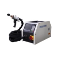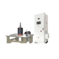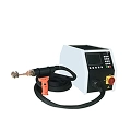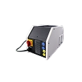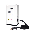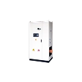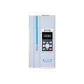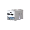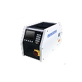





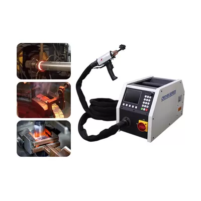
High Frequency Induction Heating is a precise, touch-free way to create fast heat inside metal parts. This process works through electromagnetic induction and Joule self-heating. Three main parts power your system: an electronic oscillator, an electromagnetic coil, and a metal workpiece that conducts electricity. Fast-switching alternating current flows through the coil to create a strong magnetic field. This field then causes swirling electrical currents to flow inside your metal part. You need to make smart design choices to get the best heat efficiency. People usually choose power frequencies between 60 kHz and 200 kHz for normal jobs, or up to 10 MHz for special uses, which helps control how deep the heat goes and balances circuit impedance.
Points clés à retenir
- Chauffage par induction quickly makes metal parts hot from the inside using electrical flow and magnetic forces.
- Engineers adjust the electrical speed to manage how far heat soaks into metal.
- Hollow copper coils require clean running water to prevent getting too hot and creating mineral deposits.
- Induction systems save energy and heat up metals much faster than traditional flame furnaces.
Principles of High Frequency Induction Heating
Faraday’s Law and Joule Heating Dynamics
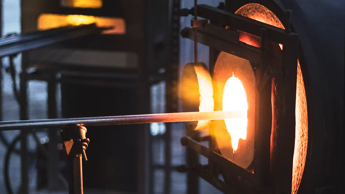
Sending fast-changing electric current through a coil creates a shifting magnetic field around it. Placing a metal part inside this field forces swirling electric loops to flow within the metal. We call these induced electrical loops eddy currents. Faraday’s Law explains how the coil interacts with your metal target. You can change the magnetic strength by adjusting the coil’s electrical flow.
The metal part naturally resists the motion of these flowing electrons inside it. This natural friction turns the electrical energy directly into real heat inside the part. Joule’s law shows this heat process using current, resistance, and time. Total resistance changes based on material type, path length, and width.
Inside the metal, total heat creation relates directly to the strength of eddy currents. Heat energy jumps up quickly when current density increases. Doubling the current density creates four times as much heat power. High Frequency Induction Heating uses high speeds to boost current strength. Faraday’s law shows that higher speeds raise current levels. This change causes heat output to jump with the square of the frequency speed. Faster frequencies pack current near the outer edge, heating your metal part very quickly.
Hysteresis Loss and Curie Point Transitions
Magnetic metals like iron and steel offer extra heating power before reaching a high warmth limit. Placing a magnetic metal in the field forces its tiny internal magnets to spin rapidly. These inner magnets rub against internal metal flaws, borders, and stress points. This microscopic friction creates hysteresis heat, which adds extra warmth to your metal part.
For ferromagnetic materials like steel, induction heating benefits from both eddy currents and hysteresis losses, making the process exceptionally fast and energy-efficient below the Curie temperature.
Heat behavior and power loss in magnetic metals change as the part gets hotter.
| Material | Temperature coefficient (α) | Loss increase per 100°C rise |
|---|---|---|
| Nickel-iron alloys | ~0.002 per °C | 20% |
| Standard silicon steels | ~0.005 per °C | 50% |
Also, hysteresis heat rises with temperature because domain walls move more easily in hotter silicon steel.
When carbon steel reaches 768°C, or 770°C for iron, its magnetic power stops completely. The metal loses its strong magnet state and follows basic paramagnetic rules. Its magnetic strength drops down to a basic level of one. At this exact point, magnetic friction heat stops completely. The heating system must then rely only on eddy currents to push temperatures higher.
Skin Depth and Frequency Optimization
Calculating Skin Depth and Current Density
You find skin depth with the equation: skin depth equals square root of (resistivity divided by (pi times frequency times magnetic permeability)). Resistivity shows electrical resistance, frequency tracks power cycle speed, and permeability measures magnetic response. High Frequency Induction Heating pushes alternating current along the outer surface of your target metal. Current density drops quickly as you move deeper inside the conductive metal piece. The symbol delta marks the point where field strength falls to 37 percent of its top value.
Over 98 percent of total current flows within four skin depths from the surface. Changing the system frequency lets you easily control how deep this current layer goes.
- Copper at 50 Hz: skin depth measures about 9.2 mm.
- Copper at 10 kHz: skin depth measures 0.65 mm.
- Copper at 100 kHz: skin depth measures 0.21 mm.
- Copper at 1 MHz: skin depth measures 65 μm.
Frequency Selection for Surface vs Through Heating
You choose your working frequency by looking at part thickness and your planned heat pattern. Normal high-frequency levels from 60 kHz to 200 kHz put heat directly into outer layers. Super-high frequencies between 1 MHz and 10 MHz create very thin heat areas. Lower frequencies running from 30 kHz to 80 kHz push eddy currents deeper inside your metal part.
Surface hardening uses high speeds from 100 kHz to 450 kHz to heat outer metal quickly. Heating large steel rods all the way through needs lower speeds to stop surface damage. Higher resistance in some steel types also helps lower the needed frequency for deep heating. Good design rules state that part size should equal four to eight skin depths for even center heating.
Inverter Circuits and Impedance Matching
Solid-state inverters turn regular plug power into fast-switching electrical current. You use organized rows of chips to create these speedy energy changes. Selecting the right parts controls how well your system warms objects up.
| Composant | Role in induction-heating inverter | Characteristics for high-frequency AC conversion |
|---|---|---|
| IGBT | Flips big power loads on and off quickly to make the strong shifting magnetic field that drives heating; it also acts as a primary power converter. | Turned on by voltage; middle-tier speed; handles big power loads well; wastes very little energy; best for medium-speed heating jobs. |
| MOSFET | Works as a speedier option inside converter setups, mainly when working with smaller power levels and faster cycle speeds. | Controlled using voltage; extremely rapid movement; manages medium power levels; loses more energy at higher voltages; great for fast, low-voltage work. |
Series and Parallel Resonant Tank Topologies
Connecting your power source to a tuned tank circuit builds the highest possible efficiency. Series setups fed by voltage run smoothest when power flow matches up easily with low energy drag. Parallel setups fed by current send strong power through thick coils while keeping things steady.
Smart tracking tools check how the timing lines up between incoming power signals. Keeping a high energy score helps hold power inside your tank system for later use. Matching networks adjust these power paths by balancing coils and stored charge as work items change.
Inverter Topologies and Canroon Power Units
Canroon supply setups deliver steady heat control using modern computer management systems. Your metal target shifts its electric traits as it gets warmer. Built-in system tools instantly change settings to keep full energy moving straight into the metal.
| Méthode | How Canroon power units support variable thermal loads |
|---|---|
| Automatic frequency tracking | The machine spots physical changes like lost magnetic pull at key heat limits, then quickly shifts power speeds to prevent energy loss and surface damage. |
| Impedance matching | A clever tank setup with power storers and custom coils tunes the target, balances power, and stops timing drops so you keep complete control over heat levels. |
| Closed-loop dynamic adjustment | Smart digital brains constantly alter power strength, speed timers, and warmth levels to fix size changes and shifting metal conditions. |
Digital control setups continually balance system power against real-time feedback from the target coil. You get identical heat patterns every single time across different metal sizes and types.
Coil Design and Thermal Management
Workhead Geometry and Coupling Distance
You must match the coil shape directly to your workpiece geometry to ensure uniform heating. Magnetic flux density drops rapidly as you increase the clearance distance between the coil turns and your metal part. Transformer coupling efficiency decreases with the square of this gap distance. Therefore, you should position your coil turns to force the maximum number of magnetic flux lines directly through the target heating zone. Placing opposite sides of a coil too close together can cancel the magnetic field and reduce total inductance.
| Heating condition | Recommended coupling gap |
|---|---|
| Static surface heating | 0.060 in (1.5 mm) |
| Progressive scanning | 0.075 in (1.9 mm) |
| Through-heating steel | 0.25–0.38 in (6.4–9.5 mm) |
Magnetic flux density is strongest near the coil turns and weaker at the geometric center. Lead junctions can also shift the magnetic center away from the geometric axis. You can rotate the part or offset the lead location to correct uneven heating patterns on long or off-center parts.
Internal Water Cooling and Flux Concentrators
Water-cooled hollow copper tubing prevents internal coil failure during continuous high-power operation. You achieve high electrical efficiency by matching the coil wall thickness to roughly one reference penetration depth. For example, tests show that a 0.048-inch wall thickness lowers coil temperature by 40°C at 3 kHz and 7500 A. Proper wall sizing optimizes power transfer while allowing sufficient cooling fluid flow.
You must maintain water purity inside your cooling channels to stop internal scale buildup and electrolysis:
- Maintain pure water near 10 µS/cm and switch it out once the level hits 100 µS/cm.
- Scrub off dirty mineral scale using soft soap and plastic tools to stop unwanted heat trapping.
- Guard thin copper tubing against freezing by adding approved glycol fluids recommended by the manufacturer.
For heavily loaded flux concentrators, remove heat by conduction to the water-cooled coil or use direct water cooling. Simulation indicates Fluxtrol 100 can operate continuously at 1 T, 1 kHz, and direct radiation from a 1200°C part when direct water cooling is used.
Industrial Applications of High Frequency Induction Heating
Metal Melting, Surface Hardening, and Tempering
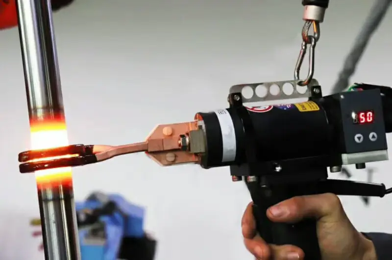
You can transform metal processing lines by integrating High Frequency Induction Heating for foundry operations and localized thermal treatments. Industrial induction systems achieve higher than 85% electrical-to-heat conversion efficiency, outperforming traditional flame furnaces. In foundry metal melting, alternating magnetic fields generate powerful eddy currents inside conductive charge material. You experience fast melting cycles alongside electromagnetic stirring, which creates uniform metal chemistry without mechanical mixing tools. Induction furnaces typically consume 500–550 kWh/ton depending on charge material, whereas electric arc furnaces often consume 400–450 kWh/ton excluding key operational trade-offs.
Automotive and aerospace manufacturers rely on targeted thermal processing to strengthen critical structural components. You can apply high-frequency fields to gears, shafts, bearings, and camshafts to achieve localized surface hardening while maintaining a tough, shock-absorbing inner core.
| Frequency band | Typical case depth | Automotive relevance |
|---|---|---|
| High frequency (100 kHz–500 kHz+) | 0.5–2.0 mm | Small, precise parts; small gears |
| Medium-high/medium frequency (10 kHz–100 kHz) | 1.5–5.0 mm | Most common for automotive crankshafts, drive shafts, and gears |
| Medium frequency (1 kHz–10 kHz) | >4.0 mm | Larger/heavy-duty parts |
Process engineers define effective case depth at the point where the microstructure contains at least 50% martensite. Selective spin hardening on automotive steel components commonly produces a surface hardness of 56–65 HRC. You can follow hardening passes with inline induction tempering or stress relieving to soften brittle zones and reduce residual internal stress.
High-Precision Brazing and Tube Welding
High Frequency Induction Heating provides fast, localized thermal energy to create high-integrity joins without damaging surrounding material. System power levels between 10–100 kW dominate this market segment because they support automotive part hardening, forging, and automated joining. You can join carbide cutting tools, saw blades, and complex pipe assemblies using precise temperature control that prevents scaling and oxidation.
| Base material | Filler-metal guidance | Temperature note |
|---|---|---|
| Tungsten carbide | Silver braze alloys with small additions of nickel and manganese wet cemented carbide surfaces | Choose the lowest possible brazing temperature to reduce residual stresses in the joint |
| PCD | Low-temperature, high-silver BAg-24; BAg-5 or BAg-7 are alternatives without nickel/manganese | Keep below 1382°F (750°C) to avoid diamond degradation |
You can use specialized sandwich alloys like Trimet, which feature a copper core between braze layers. The copper layer stays solid during heating to cushion thermal expansion stress between carbide inserts and steel bases. Applying low-temperature flux like Handy Flux B-1 Black between 1100–1700°F (593–927°C) cleans oxide layers during heating cycles.
For continuous manufacturing lines, you can run high-frequency power units to execute continuous seam tube welding at high speeds. Squeezing rollers force heated tube edges together, creating a solid forge weld along the running seam. You achieve rapid production throughput, eliminate filler metal requirements, and maintain tight thermal consistency across every finished batch.
System Troubleshooting and Maintenance
Load Mismatch and Frequency Drift
Your induction heating cycle constantly alters the effective impedance of the tank circuit. Workpiece electrical resistance rises as temperatures increase. Ferromagnetic materials undergo large shifts in magnetic permeability. Small mechanical movements also change the coupling gap between your coil and the target workpiece. Replacement coils with millimeter-level geometric variations modify system inductance and stray coupling. High-Q loads suffer extreme sensitivity to these physical shifts. Minor detuning creates massive swings in circulating current and tank voltage.
| Failure mode | Operational cause / consequence |
|---|---|
| Incorrect frequency specification | Too low causes eddy-current cancellation; too high concentrates power at the surface. |
| Geometric mismatch | Running square billets in round coil liners creates uneven air gaps and degrades efficiency. |
| Aggressive heating | Thermal stresses initiate cracks in as-cast materials from inclusions or porosity. |
| Skid rail degradation | Excessive billet weight crushes tubing, restricting water flow and causing rail burnout. |
Adjusting the matching inductor inside an L-match network changes your resonant frequency. The system power factor falls when the natural resonant frequency moves above the inverter drive frequency. This condition forces load current to lead the voltage. Leading current triggers reverse recovery in free-wheel diodes while they carry forward current. This process generates destructive current spikes through opposing MOSFETs. You must deploy automatic frequency tracking to protect power components from catastrophic failure.
Preventive Care for Canroon Systems
You can maximize power supply reliability by building a disciplined preventive care schedule. Base your baseline maintenance on original manufacturer specifications. Set planned service intervals at 80–90% of mean time between failures for critical plant assets. Perform quarterly visual panel inspections, quarterly GFCI/AFCI tests, and quarterly UPS battery checks. Execute monthly load tests on emergency generators. Conduct annual thermographic scans on electrical panels, re-torque hardware connections, and test insulation resistance on transformers.
Inspect your induction coils frequently to prevent unplanned thermal shutdowns. Thermal cycling, physical wear, and vibration cause electrical arcing and coolant leaks over time. A dangerous vapor layer forms when inner inductor surface temperatures exceed 250°C. This vapor layer degrades thermal transfer and triggers rapid copper failure. Perform infrared thermographic surveys on active switchgear under at least 40% load every three years. Align all facility procedures with NFPA 70B, NFPA 70E, and OSHA 1910 Subpart S requirements.
High Frequency Induction Heating relies on the physical links between frequency, skin depth, magnetic traits, and thermal efficiency. You optimize your thermal operation by tuning tank circuits, shaping coil geometries accurately, and running active water cooling systems.
High-efficiency digital power electronics, including Canroon induction power units, maintain a robust power factor and provide precise process control during changing thermal loads. Future manufacturing integrates robotics, smart workflow automation, and real-time temperature sensing for automated quality control. Advanced power converter designs push total system efficiency past 90% while reducing energy waste by more than 35%. You achieve repeatable heating, lower factory emissions, and lower costs.
FAQ
What happens when steel reaches its Curie point during induction heating?
Steel loses its magnetic traits at 768°C. Magnetic friction heat stops completely at this temperature threshold. Your induction system must then rely only on induced eddy currents to continue heating the part to higher temperatures.
How do you choose the right frequency for surface hardening versus through-heating?
You select high frequencies from 100 kHz to 450 kHz for shallow surface hardening because fast cycles concentrate heat near the outer surface. You select lower frequencies between 30 kHz and 80 kHz for deep heat penetration to warm large parts through to the center.
Why must you maintain high water purity in coil cooling systems?
Pure water prevents mineral scale buildup inside your hollow copper coils. You maintain initial water purity near 10 µS/cm. You must replace the cooling water once contamination drives conductivity to 100 µS/cm to prevent heat trapping and copper coil burnout.
What efficiency advantages does induction heating offer over traditional furnaces?
Industrial induction systems achieve electrical-to-heat conversion efficiencies above 85%. You generate heat directly inside the workpiece without flame losses. This fast process cuts overall power consumption, reduces atmospheric emissions, and guarantees consistent thermal results across every manufacturing batch.