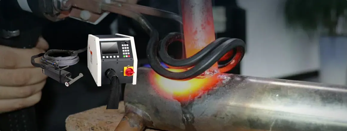
Induction heating coil design plays a critical role in determining the efficiency, heating uniformity, energy consumption, and overall performance of an induction heating system.
Whether used for metal hardening, brazing, forging, melting, or heat treatment, a well-designed induction coil ensures optimal electromagnetic coupling between the coil and the workpiece, resulting in faster heating cycles and improved process reliability. However, achieving maximum efficiency requires careful consideration of multiple design factors, including coil material, geometry, diameter, number of turns, and spacing.
In this guide, we will explore how induction heating coils should be designed and provide practical tips for selecting the most suitable coil configuration for different industrial applications. By understanding these key design parameters, engineers and manufacturers can enhance heating performance, reduce operational costs, and extend equipment lifespan.
Basic Knowledge of Induction Heating Coil Design
Induction heating coil design is a foundational aspect of an induction heating system; it determines how electrical energy is converted into a magnetic field and subsequently influences the heating behavior of the workpiece. Before delving into specific design parameters—such as materials, geometry, or structural optimization—it is essential to understand the basic definitions, operating mechanisms, and the logic governing the coil’s overall impact on the heating process.
What is an induction heating coil?
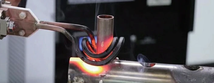
The induction heating coil is the core component of an induction heating system responsible for execution; essentially, it is a conductor structure designed to generate an alternating magnetic field. Typically wound from copper tubing or wire and connected to a high-frequency power supply, it creates a stable electromagnetic field environment when energized.
In terms of system architecture, the induction heating coil serves as the “energy conversion interface,” and its operational pathway can be broken down as follows:
- The power supply outputs high-frequency alternating current.
- Current flowing through the coil generates an alternating magnetic field.
- The magnetic field acts on the workpiece, inducing an electric current (eddy current).
- Internal resistance within the workpiece generates heat, resulting in heating.
From a functional perspective, the coil can be viewed as a “non-contact heating tool,” offering the following advantages:
- No direct contact with the workpiece which can reduces contamination and wear
- Controllable heating zone which means strong localized heating capability
- Rapid response that suitable for automated production
In industrial applications, different types of coils correspond to specific heating tasks:
| Coil Type | Structural Characteristics | Application Scenario |
| Helical Coil | Multi-turn cylindrical structure | Heating shafts and rods |
| Flat Coil | Single- or multi-layer flat structure | Heating thin sheets and surfaces |
| Internal Coil | Insertable structure | Heating inner pipe walls |
| Shaped Coil | Customized structure | Matching specialized workpieces |
Key Insight: The coil is not merely an “accessory component” but a critical execution unit that directly determines the heating outcome.
Working Principle of Induction Heating Coils
Induction heating is essentially a process combining electromagnetic induction and resistance heating; its core principles can be broken down into two physical mechanisms:
Electromagnetic Induction: Generation of Eddy Currents
When high-frequency current flows through the coil, it generates an alternating magnetic field. This magnetic field acts upon the metal workpiece, inducing closed-loop currents (eddy currents) within the workpiece in accordance with the laws of electromagnetic induction.
Key points:
- Higher frequency → Eddy currents become more concentrated (enhanced skin effect)
- Higher magnetic field strength → Greater induced current
Resistance Effect: Generation of Heat
As eddy currents flow within the workpiece, they encounter the material’s electrical resistance, converting the electrical energy into thermal energy.
Heat calculation logic:
- Heat ∝ Current² × Resistance
- Materials with poor conductivity → Generate heat more readily
- High frequency → Surface heating is more pronounced
Skin Effect
At high frequencies, the current tends to concentrate on the material surface, resulting in a “surface heating” phenomenon.
- Frequency Range Heating Depth
- Low Frequency Deep Heating
- Medium Frequency Medium Depth
- High Frequency Surface Heating
This directly determines that the coil design must match the application target; otherwise, problems such as “insufficient heating” or “overheating” will occur.
Why Coil Design Affects Heating Efficiency
Many people focus on “power supply” when understanding induction heating, but the actual efficiency difference often stems from coil design.
The fundamental reason is:
The coil determines the magnetic field distribution, and the magnetic field determines the energy transfer efficiency.
This can be understood from three core dimensions:
Magnetic field coupling efficiency
There is a “coupling relationship” between the coil and the workpiece, similar to the primary and secondary windings in a transformer.
Influencing Factors:
- Coil-workpiece distance (closer is more efficient)
- Coil shape and workpiece matching degree
- Magnetic field leakage
| Coupling state | Energy utilization rate |
| Tight fit | High |
| Excessive gap | Low |
| Shape mismatch | Extremely low |
Power loss control
The coil itself also generates losses, mainly including:
- Resistance loss (heating)
- Skin effect leading to reduced effective conductive area
- Proximity effect (inter-turn interference)
Optimization direction:
- Use highly conductive materials (copper)
- Use water-cooling structure to reduce temperature rise
- Control inter-turn distance to reduce interference
Heat distribution uniformity
The coil structure directly affects the heating area:
- Uneven turn distribution → Uneven heating
- Excessively strong local magnetic field → Local overheating
- Coil offset → Hot zone offset
Typical problems:
- Decreased surface quality
- Workpiece deformation
- Uneven welding
Core conclusion
| Design dimension | Influencing results | Optimization direction |
| Geometric shape | Magnetic field distribution | Matching workpiece contour |
| Number of turns | Magnetic field strength | Balancing efficiency and losses |
| Spacing | Magnetic field uniformity | Avoiding localized concentrations |
| Materials | Power loss | highly conductive copper |
| Distance | Coupling efficiency | as close to the workpiece as possible |
Many design philosophies assume “the more complex the coil, the better,” but the reality is:
The goal of coil design is not complexity, but matching:
- Matching with the workpiece
- Matching with the frequency
- Matching with the power
If these three are inconsistent, even high power cannot be converted into effective heat energy.
Key Factors Affecting Induction Heating Coil Efficiency
Induction heating efficiency is essentially the ratio of input electrical energy to workpiece heat energy. During coil design, without clearly controlling key variables, situations can easily arise where “power is sufficient but heating effect is poor.”
The Influence of Frequency on Heating Efficiency
Frequency determines the distribution of the electromagnetic field, directly affecting the location of heat generation.
Core Mechanism:
- High frequency → Current concentrates on the surface (skin effect)
- Low frequency → Current penetrates deep into the interior (deep heating)
If the frequency does not match the workpiece thickness, the following will occur:
- Too high a frequency → Only the surface is heated, internal temperature is insufficient
- Too low a frequency → Heating is slow, efficiency decreases
| Frequency Range Heating | Characteristics Applicable Scenarios |
| Low frequency (1–10 kHz) | Deep heating Large workpieces |
| Medium frequency (10–100 kHz) | Balanced heating General industrial applications |
| High frequency (100 kHz+) | Surface heating Surface hardening, thin parts |
Key Control Logic: Higher frequency is not always better; it must match the workpiece size and heating depth.
Coupling Degree Between Coil and Workpiece
Coupling efficiency determines whether magnetic field energy is effectively utilized and is one of the most direct factors affecting efficiency.
Core variables affecting coupling:
- Coil-workpiece distance
- Coil coverage degree
- Geometric matching degree
The coupling relationship can be compared to a “transformer structure”:
| State | Description | Efficiency Performance |
| Tight coupling | Fits the workpiece shape | High efficiency |
| Excessive gap | Severe magnetic field leakage | Low efficiency |
| Eccentric layout | Uneven magnetic field | Local overheating |
A key misconception:
Many designs default to “leaving a safe distance,” but increasing the distance directly reduces energy transfer efficiency.
Coil Resistance and Energy Loss
Coils not only transmit energy but also consume it.
Main sources of loss:
- Resistive loss (I²R loss)
- Skin effect reduces effective conductive area
- Proximity effect causes uneven current distribution
Impact effects:
- Coil self-heating
- Decrease in effective output power
- Reduced system efficiency
Optimization directions:
- Use high conductivity materials (copper)
- Use a hollow water-cooling structure to reduce temperature rise
- Control conductor cross-sectional area
| Factors | Influencing Mechanisms | Optimization Methods |
| Resistance | Converted to ineffective heat | Increase conductivity |
| Temperature rise | Increase resistance | Enhance cooling |
| High-frequency effects | Limit current distribution | Optimize cross-sectional structure |
Uniformity of Magnetic Field Distribution
Magnetic field distribution determines heat distribution and is crucial to “heating quality.”
Common Problems:
- Uneven coil distribution → Hot spot concentration
- Local coil bending → Magnetic field shift
- Asymmetrical structure → Uneven temperature
Results:
- Workpiece deformation
- Local overheating
- Inconsistent heating
| Distribution | Heat Performance |
| Uniform Magnetic Field | Uniform Temperature |
| Local Enhancement | Local Overheating |
| Shifted Magnetic Field | Heating Shift |
Fundamental Logic: Uneven Magnetic Field = Uneven Heat Distribution
Influence of Material Electromagnetic Properties on Efficiency
Different materials exhibit significantly different responses to induction heating.
Key Parameters:
- Electrical Conductivity
- Magnetic Permeability
- Resistivity
Material Classification Influence:
| Material Type | Heating Characteristics | Efficiency Performance |
| Ferromagnetic Materials (Steel) | Prone to Hysteresis Loss | High Efficiency |
| Non-ferromagnetic Materials (Aluminum, Copper) | Relies Only on Eddy Currents | Relatively Low |
| High-Resistance Materials | Prone to Heat Generation | High Efficiency |
An Easily Overlooked Point: The same coil design can exhibit completely different performance on different materials.
Power Matching and System Stability
Input power determines the theoretical heating capacity, but efficiency depends on the “degree of matching”.
Mismatch Manifestations:
- Excessive power → Energy waste, overheating
- Insufficient power → Inadequate heating
System Problems:
- Resonance misalignment
- Power factor deterioration
Unstable load
| Matching Status | System Performance |
| Good matching | High efficiency and stability |
| Mismatch | High energy loss |
| Dynamic changes | Unstable output |
Key Insight: The core determinant of efficiency is not power, but matching.
Structural Summary: Core Variable Model Influencing Efficiency
Abstracting all factors into three core dimensions:
| Dimension | Included Factors | Essential Role |
| Electromagnetic parameters | Frequency, material | Determines energy generation method |
| Structural parameters | Coil shape, spacing | Determines energy transfer path |
| System parameters | Power, matching | Determines energy utilization rate |
Selecting the Optimal Material for Induction Heating Coils
The induction heating coil is the core component of an induction heating system, and its material selection directly affects energy transfer efficiency, heat loss, equipment lifespan, and operational stability. Because the coil needs to withstand high-frequency, high-current, and continuous heating for extended periods, factors such as conductivity, heat dissipation capacity, mechanical strength, corrosion resistance, and manufacturing cost must be comprehensively considered during the design process.
A reasonable selection of coil materials can not only improve induction heating efficiency but also reduce energy loss and maintenance costs, providing a good foundation for subsequent optimization of coil size, number of turns, and structure.
Requirements for Induction Heating Coil Materials
High-quality induction heating coil materials should typically possess the following characteristics:
- High conductivity, reducing resistance loss
- Good thermal conductivity, improving heat dissipation efficiency
- Sufficient mechanical strength to prevent deformation during long-term operation
- Good high-temperature resistance
- Strong oxidation and corrosion resistance
- Easy to bend, process, and weld
- Able to adapt to cooling system design requirements
For high-power induction heating equipment, conductivity and heat dissipation performance are often the two most critical indicators.
Comparison of Common Induction Heating Coil Materials
Currently, copper and its alloys are the most commonly used materials in industrial induction heating equipment. Different materials are suitable for different application scenarios.
| Material Type | Electrical Conductivity | Thermal Conductivity | Cost | Applicable Scenarios |
| Pure Copper (Oxygen-Free Copper) | Extremely High | Extremely High | Medium | Most Induction Heating Equipment |
| Electrolytic Copper | Very High | Very High | Low | General Industrial Heating |
| Copper Alloy | Medium | Medium | High | High-Intensity Special Working Conditions |
| Aluminum | High | High | Low | Low-Power Equipment |
| Silver-Plated Copper | Extremely High | Extremely High | Very High | High-Frequency Precision Heating Systems |
From a comprehensive performance perspective, pure copper remains the preferred material in the vast majority of induction heating coil designs.
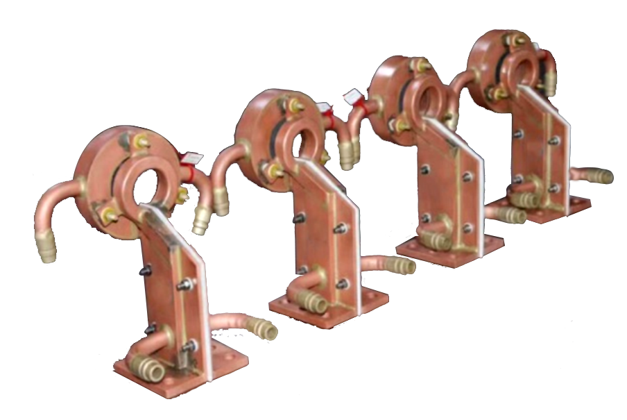
Why is Copper the Preferred Material for Induction Heating Coils?
In the induction heating industry, copper tube coils occupy an absolutely mainstream position. Their advantages are mainly reflected in the following aspects:
Extremely Low Resistance Loss
Copper has excellent electrical conductivity, which can effectively reduce Joule heat loss generated when high-frequency current passes through the coil, thereby improving the overall system efficiency.
Excellent Heat Dissipation Capacity
Induction heating coils generate a large amount of heat during operation. Copper material can quickly conduct heat, and with a water cooling system, the coil can maintain stable operation.
Easy to Process and Shape
Copper tubes can be easily bent into spiral, disc, rectangular, or irregular shapes to meet the heating requirements of different workpieces.
Good Service Life
Under proper cooling conditions, copper coils can operate stably for long periods, reducing downtime for maintenance.
Difference Between Oxygen-Free Copper and Ordinary Copper
For high-frequency induction heating equipment, oxygen-free copper (OFC) generally performs better than ordinary electrolytic copper.
| Performance Indicators | Oxygen-Free Copper | Ordinary Electrolytic Copper |
| Copper Purity | ≥99.95% | Approximately 99.90% |
| Conductivity | Higher | Relatively High |
| Oxidation Resistance | Better | Average |
| High-Frequency Performance | Excellent | Good |
| Service Life | Longer | Relatively Long |
| Cost | Higher | Lower |
When the equipment operates at high frequencies or for long periods of continuous operation, oxygen-free copper often achieves better long-term stability and energy efficiency.
The Influence of Skin Effect on Materials in High-Frequency Induction Heating
In high-frequency induction heating, the alternating current mainly flows on the surface of the coil; this phenomenon is called the “skin effect.”
As the frequency increases:
- Current concentrates in a thinner conductor surface layer
- Effective conductor cross-sectional area decreases
- Resistance increases
- Heat loss increases
Therefore, high-frequency equipment requires materials with high conductivity to reduce the additional energy loss caused by the skin effect.
Higher material conductivity:
- Higher current transmission efficiency
- Lower heat loss
- Higher power output utilization
- Faster heating speed
This is also an important reason why high-purity copper tubes are commonly used in high-frequency induction equipment.
Common Misconceptions in Material Selection
The following problems are common in coil design:
- Focusing only on material price while ignoring conductivity
- Using copper tubes with excessively thin walls
- Neglecting cooling system design
- Using low-purity copper instead of high-purity copper
- Using unsuitable low-conductivity materials in high-frequency equipment
These problems can lead to excessive coil temperature rise, decreased efficiency, or even premature damage.
Summary
The selection of induction heating coil materials is a crucial factor affecting system performance. High electrical conductivity, high thermal conductivity, and good heat dissipation are the core criteria for material selection. For most industrial induction heating equipment, oxygen-free copper water-cooled tubes remain the ideal choice.
Choosing the Appropriate Induction Coil Geometry
The alternating magnetic field generated by the induction coil creates eddy currents inside the workpiece, and the coil’s geometry determines the distribution and concentration of the magnetic field. A well-designed coil structure can improve magnetic field utilization, converting more electrical energy into workpiece heat, thereby increasing overall heating efficiency.
For industrial induction heating equipment, coil shape design typically requires comprehensive consideration of workpiece size, heating area, production cycle time, and automation requirements.
Why is coil geometry so important?
The coil structure directly affects the following key performance characteristics:
- Uniformity of magnetic field distribution
- Electromagnetic coupling efficiency
- Heating depth control
- Local heating accuracy
- Energy loss level
- Production efficiency
- Workpiece temperature consistency
If the coil structure does not match the workpiece shape, the following may occur:
- Local overheating
- Heating blind zone
- Uneven temperature distribution
- Increased energy consumption
- Extended heating time
Therefore, coil shape design is often one of the most important factors affecting the induction heating effect.
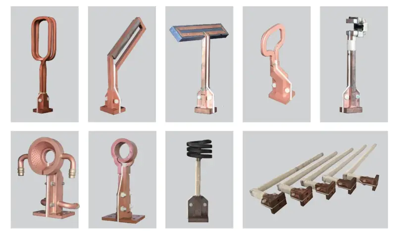
Common Induction Heating Coil Geometry
Based on industrial application requirements, common induction coils mainly include the following types:
| Coil Type | Structural Characteristics | Applicable Workpieces |
| Helical Coil | Multi-turn cylindrical structure | Shafts, rods, tubes |
| Disc Coil | Planar helical structure | Disks, plates |
| Rectangular Coil | Square or rectangular structure | Square tubes, plates |
| U-shaped Coil | Open structure | Localized heating |
| Horseshoe Coil | Bipolar structure | Edge heating |
| Ring Coil | Fully enclosed structure | Cylindrical workpieces |
| Irregularly Shaped Coil | Customized structure | Special workpieces |
Different coil shapes are suitable for different heating targets. There is no absolutely optimal solution, only the design most suitable for the specific application scenario.
Helical Coil
The helical coil is the most common structure in induction heating equipment.
Main Features
- Simple structure
- Low manufacturing cost
- Uniform magnetic field distribution
- Easy water-cooling design
- Suitable for continuous production
Typical Applications
- Steel bar heating
- Shaft quenching
- Tube heating
- Forging preheating
Advantages
- High heating efficiency
- High power utilization
- Easy maintenance
Limitations
- Not suitable for complex irregularly shaped workpieces
- Limited local heating capacity
Pancake Coil
Palm coils are typically composed of single-layer or multi-layer planar helical structures.
Main Features
- Magnetic field concentrated directly in front of the coil
- Significant surface heating effect
- Suitable for planar workpieces
Typical Applications
- Metal sheet heating
- Disc workpiece heating
- Welding preheating
- Surface hardening treatment
Advantages
- Concentrated heat
- Fast heating speed
- Suitable for high-frequency systems
Limitations
- Limited heating depth
- Not suitable for long workpieces
Rectangular Coil
Rectangular coils are specifically designed for square or rectangular workpieces.
Applicable Objects
- Square steel
- Square tube
- Long strip workpieces
- Mold parts
Design Advantages
- Improved magnetic field coverage
- Reduced corner temperature difference
- Improved heating uniformity
Compared to circular coils, rectangular coils can better fit the contour of square workpieces, thus improving coupling efficiency.
U-shaped Coils and Horseshoe Coils
For localized heating processes, open coil structures have significant advantages.
U-shaped Coil Characteristics
- Open structure
- Easy to automate integration
- Controllable heating area
Horseshoe Coil Characteristics
- Highly concentrated magnetic field
- Strong localized heating capability
- Low energy consumption
Common Applications
- Gear tooth surface quenching
- Weld preheating
- Edge heating
- Localized annealing
Circular Coil Design
Circular coils can achieve 360° uniform heating of workpieces.
Main Features
- Symmetrical magnetic field
- Uniform temperature distribution
- High energy utilization
Common Applications
- Bearing heating
- Hot fitting of cylindrical workpieces
- Ring component heating
- Sleeve heating
For batch production processes requiring high consistency, circular coils typically achieve better heating results.
Irregular Coil Design
With the development of the automotive, aerospace, and precision manufacturing industries, more and more workpieces require customized coil structures.
Common Irregular Coil Forms
- Elliptical Coil
- Polygonal Coil
- Double-Layer Composite Coil
- Three-Dimensional Coil
- Multi-Region Independent Coil
Applicable Scenarios
- Crankshaft Heating
- Gear Quenching
- Complex Mold Heating
- Special Welding Processes
Irregular coils can maximize magnetic field utilization, but manufacturing costs and design difficulties are also relatively high.
Relationship between Coil Shape and Heating Uniformity
When selecting coil geometry, priority should be given to ensuring that the magnetic field coverage matches the workpiece contour height.
| Workpiece Shape | Recommended Coil |
| Round Bar | Helical Coil |
| Tube | Toroidal Coil |
| Disc | Disc-shaped Coil |
| Square Steel | Rectangular Coil |
| Gear | U-shaped Coil |
| Weld | Horseshoe-shaped Coil |
| Irregularly Shaped Parts | Custom-made Irregularly Shaped Coil |
Generally speaking:
- The closer the coil shape is to the workpiece shape
- The stronger the electromagnetic coupling
- The higher the thermal efficiency
- The better the temperature uniformity
Factors to Consider When Selecting Coil Geometry
In actual engineering design, the following factors should be comprehensively evaluated:
Workpiece Dimensions
The outer diameter, length, and thickness of the workpiece directly affect the selection of the coil structure.
Heating Area
Determine whether overall heating or localized heating is required.
Operating Frequency
Different frequencies correspond to different magnetic field distribution characteristics.
Automation Requirements
Production line equipment usually requires coil structures that facilitate robotic arm operation.
Cooling System Design
Complex coils require sufficient space for water cooling channels.
Manufacturing Costs
While irregularly shaped coils offer higher efficiency, they also have higher manufacturing costs.
Common Errors in Coil Geometry Design
The following problems should be avoided during the design process:
- Excessive gap between the coil and the workpiece
- Coil size significantly larger than the workpiece size
- Ignoring workpiece edge effects
- Blindly increasing structural complexity
- Failing to consider cooling pipe layout
- Not matching the actual heating area
These problems will all lead to a decrease in magnetic field utilization, thereby reducing overall heating efficiency.
Summary
The geometry of the induction coil is a crucial factor affecting magnetic field distribution and heating effect. Helical coils are suitable for most cylindrical workpieces, disc coils are suitable for planar heating, rectangular coils can improve the coupling efficiency of square workpieces, while U-shaped, horseshoe-shaped, and irregularly shaped coils can meet the needs of localized heating and special processes.
How to Select the Optimal Coil Diameter
After determining the coil geometry, the next key parameter to optimize is the coil diameter. The coil diameter determines the relative position between the coil and the workpiece, directly affecting magnetic field coupling efficiency, heating uniformity, and energy utilization.
In many induction heating systems, even with reasonable coil material and structural design, improper coil diameter selection can still lead to slow heating rates, uneven temperature distribution, or energy waste.
Therefore, selecting the appropriate coil diameter is crucial for improving induction heating efficiency.
Why is the coil diameter so important?
The coil diameter determines the degree of magnetic coupling between the magnetic field and the workpiece.
From the perspective of electromagnetic induction:
- If the coil diameter is too large, the magnetic field is easily dispersed.
- If the coil diameter is too small, the magnetic field coverage is insufficient.
- A suitable diameter can achieve optimal energy transfer.
Key indicators affected by coil diameter:
| Influencing factors | Effects |
| Magnetic field strength | Affects heating rate |
| Energy coupling efficiency | Affects energy consumption |
| Temperature uniformity | Affects product quality |
| Heat distribution range | Affects the heating area |
| Equipment operating costs | Affects overall efficiency |
Relationship between coil diameter and workpiece size
In practical design, the coil diameter usually needs to be reasonably matched with the workpiece size.
The basic principle is:
The coil should be as close to the workpiece as possible, but not in contact with it.
A smaller gap usually means higher magnetic field utilization and faster heating speed.
Coil and Workpiece Matching Effect
Matching Status Heating Effect
| Proper Diameter Matching | High-Efficiency Heating |
| Coil Too Large | Magnetic Field Diffusion, Efficiency Decrease |
| Coil Too Small | Heating Area Limited |
| Close Contact | Safety Risks Possible |
Common Workpiece and Coil Diameter Matching Principles
| Workpiece Type | Diameter Design Principle |
| Round Bar | Coil inner diameter slightly larger than workpiece diameter |
| Tube | Maintain uniform annular gap |
| Shaft Parts | Ensure magnetic field covers the target area |
| Ring Parts | Consider both inner and outer surface heating requirements |
What problems arise from an excessively large coil diameter?
Many beginners tend to design larger coils to accommodate workpieces of different sizes, but excessively large coils usually reduce heating efficiency. Common effects include:
Dispersed magnetic field
The magnetic field cannot be concentrated on the workpiece.
This leads to:
- Decreased energy utilization
- Extended heating time
- Increased power consumption
Increased magnetic leakage
Some parts of the magnetic field cannot effectively act on the workpiece.
This manifests as:
- Decreased equipment efficiency
- Increased cooling load
- Increased operating costs
Poor temperature uniformity
Excessively large coils may cause:
- An excessively wide heating area
- Uneven heat distribution
- Increased local temperature differences on the workpiece
What problems arise from an excessively small coil diameter?
While smaller coils are beneficial for increasing magnetic field strength, an excessively small diameter can also have negative effects. Common problems include:
Insufficient heating coverage
The magnetic field cannot cover the entire target area.
Possible consequences:
- Localized overheating
- Uneven overall heating
Insufficient clamping space
A coil that is too small will affect:
- Workpiece loading and unloading efficiency
- Automated production cycle time
Increased mechanical safety risks
A coil that is too close to the workpiece may cause:
- Collision risk
- Coil damage
- Cooling system failure
How to determine a reasonable coil inner diameter?
In practical engineering design, the coil inner diameter is usually determined first.
Design Principles
The coil inner diameter should be slightly larger than the maximum outer diameter of the workpiece.
Design Objectives
- Ensure sufficient magnetic field coupling
- Reserve safe operating space
- Facilitate workpiece entry and exit
Recommended Design References
| Workpiece size | Recommended configuration |
| Small workpieces | Minimize gap |
| Medium workpieces | Maintain uniform gap |
| Large workpieces | Ensure stable magnetic field coverage |
Factors Affecting Inner Diameter Selection
- Workpiece dimensional tolerances
- Thermal expansion space
- Automated feeding requirements
- Mechanical positioning accuracy
- Cooling structure requirements
Coil Diameter Selection Process
To improve design efficiency, the coil diameter can be determined according to the following steps:
Step 1: Measure Workpiece Dimensions
Determine:
- Dimensional tolerances
- Maximum outer diameter
- Heating area length
Step 2: Determine Process Objectives
Clarify:
- Overall heating
- Local heating
- Surface heat treatment
Step 3: Evaluate Equipment Conditions
Consider:
- Power rating
- Installation space
- Automation requirements
Step 4: Optimize Diameter Design
Objectives:
- Improve coupling efficiency
- Ensure safe clearance
- Achieve uniform heating
Summary
The coil diameter is an important design parameter affecting magnetic field coupling efficiency and heating performance. An ideal coil diameter should be reasonably matched to the workpiece dimensions, ensuring safe operating space while achieving the highest possible energy transfer efficiency.
Determining the Appropriate Number of Coil Turns
After determining the coil material, geometry, and diameter, the number of coil turns becomes one of the key parameters affecting induction heating performance. The number of coil turns not only determines the magnetic field strength and induced voltage but also affects system impedance matching, heating depth, and energy utilization efficiency.
Too few turns may lead to insufficient magnetic field, while too many turns may increase coil inductance and energy loss. Therefore, in the design of induction heating coils, rationally determining the number of coil turns is an important step in obtaining optimal heating effects.
The Role of Coil Turns in Induction Heating
Induction heating coils are essentially excitation coils in electromagnetic induction systems.
When a high-frequency alternating current flows through the coil, an alternating magnetic field is generated, inducing eddy currents inside the workpiece, thereby achieving heating.
The number of coil turns directly affects:
- Magnetic field strength
- Inductance value
- Coupling efficiency
- Output power
- Heating uniformity
- System resonance state
- Energy transfer efficiency
A reasonable number of turns design can improve the workpiece’s ability to absorb energy, thereby shortening heating time and reducing energy consumption.
Relationship between Coil Turns and Magnetic Field Strength
Under the same current conditions:
- Increasing the number of turns increases the magnetic field strength.
- Decreasing the number of turns weakens the magnetic field strength.
Generally:
| Changes in Coil Turns | Magnetic Field Strength |
| Increase | Increases |
| Decrease | Decreases |
However, a higher magnetic field strength is not always better.
If there are too many turns:
- Inductance increases
- Current decreases
- Power output is limited.
Therefore, a balance needs to be found between magnetic field strength and current output.
Potential Problems with Insufficient Turns
Some designers use a very low number of turns design to reduce coil impedance.
This approach may lead to:
Insufficient magnetic field coverage
The workpiece cannot receive sufficient magnetic flux.
Decreased heating efficiency
Insufficient generation of induced eddy currents.
Uneven temperature distribution
Localized uneven heating and cooling is likely to occur.
Reduced power utilization
Some output power cannot be effectively transferred to the workpiece.
Common issues include:
- Slow heating rate
- Difficulty in heating the workpiece
- Low power output
Problems caused by excessive turns
While increasing the number of turns can enhance the magnetic field, too many turns can also have negative effects.
Significantly increased inductance
Increased coil impedance.
Decreased current
Limited output capacity of the induction heating system.
Increased copper losses
Intensified coil self-heating.
Difficulty in resonant matching
Affected power supply efficiency.
Common phenomena:
- Increased coil temperature rise
- Abnormal power supply load
- Decreased heating efficiency
- Insufficient power output from the equipment
Therefore, the number of turns design must be optimized in conjunction with frequency and power.
Recommended Turns Range at Different Frequencies
The operating frequency significantly affects the selection of the coil turns.
Generally, the higher the frequency, the fewer turns are required.
| Operating Frequency | Recommended Turns |
| 1-10 kHz | 5-15 turns |
| 10-50 kHz | 3-10 turns |
| 50-100 kHz | 2-8 turns |
| 100-500 kHz | 1-5 turns |
| Above 500 kHz | 1-3 turns |
In actual design, the following should also be considered:
- Workpiece size
- Heating depth
- Output power
- Coil diameter
Comprehensive adjustments are needed.
Turns Selection for Different Workpiece Sizes
Larger workpieces generally require more turns to create sufficient magnetic field coverage.
| Workpiece Type | Recommended Turns |
| Small parts | 1-3 turns |
| Bolts and nuts | 2-5 turns |
| Gears | 3-8 turns |
| Shafts | 5-10 turns |
| Steel bars | 6-12 turns |
| Forged billets | 8-15 turns |
A reasonable magnetic field coverage range can significantly improve energy coupling efficiency.
Relationship between Coil Turns and Heating Depth
The number of turns also affects the internal heat distribution of the workpiece.
General rules are as follows:
Fewer turns
Characteristics:
- Concentrated magnetic field
- High power density
- Fast heating rate
Suitable for:
- Surface hardening
- Localized heating
- High-frequency induction heating
More turns
Characteristics:
- Wide magnetic field coverage
- Uniform heat distribution
Suitable for:
- Overall heating
- Through-heating
- Forging preheating
Therefore, the number of turns will vary depending on the heating target.
Coil Turns and Power Matching Principles
In coil design, the number of turns must be reasonably matched with the power of the equipment.
| Power Rating | Common Turns Range |
| 5-20 kW | 2-5 turns |
| 20-50 kW | 3-8 turns |
| 50-100 kW | 5-10 turns |
| Above 100 kW | 8-15 turns |
Note: High-power equipment does not necessarily require increased turns.
Design goals should be:
- Maintaining optimal resonance
- Improving electromagnetic coupling efficiency
- Reducing ineffective losses
Factors to Consider When Calculating Coil Turns
In actual engineering design, the number of turns usually needs to be determined in conjunction with multiple parameters.
These mainly include:
- Workpiece size: Affects the magnetic field coverage.
- Heating depth: Affects magnetic field penetration requirements.
- Operating frequency: Determines the degree of skin effect.
- Output power: Affects current and magnetic field strength.
- Coil diameter: Affects electromagnetic coupling distance.
- Workpiece material: Different materials have significantly different permeability.
For example:
- Carbon steel
- Stainless steel
- Copper
- Aluminum
The required number of turns may vary significantly.
Common Turns Reference for Induction Heating Applications
The following are common industry design experience values
| Application Scenarios | Common Turns |
| Gear quenching | 2-5 turns |
| Shaft surface quenching | 3-6 turns |
| Bolt heating | 2-4 turns |
| Pipe brazing | 3-8 turns |
| Steel bar through heating | 6-12 turns |
| Forging heating | 8-15 turns |
| Smelting coil | 10-20 turns |
These data are for preliminary design reference only and ultimately require optimization through actual testing.
Common Errors in Coil Turns Design
The following problems are common in induction heating coil design:
Blindly increasing the number of turns
Leading to excessive inductance.
Completely copying experience values
Ignoring differences in equipment parameters.
Ignoring frequency variations
Causing impedance mismatch.
Not considering workpiece size
Leading to insufficient magnetic field coverage.
Ignoring resonant system matching
Reducing overall efficiency.
These issues can all lead to unstable heating effects and energy waste.
Engineering Design Recommendations
To achieve optimal design results, the following principles are recommended:
- Determine the workpiece size and heating area.
- Select a basic turns range based on the frequency.
- Optimize in conjunction with the coil diameter.
- Complete resonance matching calculations.
- Verify the design through prototype testing.
- Fine-tune the turns number based on the temperature distribution results.
This design process can effectively improve the success rate of coil development.
Summary
The number of coil turns is a crucial parameter affecting induction heating efficiency, magnetic field strength, and system matching. Too few turns will result in insufficient magnetic field, while too many turns may increase inductance and energy loss. In actual design, the optimal number of turns needs to be determined comprehensively by considering the operating frequency, workpiece size, power rating, and heating depth.
Optimizing Coil Spacing for Maximum Efficiency
After determining the coil material, geometry, diameter, and number of turns, coil spacing becomes the final critical structural parameter affecting induction heating performance. Many engineers focus on coil diameter and number of turns when designing induction heating coils, neglecting the significant impact of coil spacing on magnetic field distribution and heat uniformity.
In fact, even with the same power, frequency, and number of turns, different coil spacings can lead to drastically different heating effects. Therefore, optimizing coil spacing is crucial for improving induction heating efficiency, reducing energy loss, and enhancing workpiece temperature uniformity.
What is Coil Spacing?
Coil spacing refers to the distance between the centers of two adjacent coil turns.
Typically:
Coil Spacing = Conductor Outer Diameter + Turn Gap
For example:
- Copper tube diameter: 8 mm
- Turn gap: 2 mm
- Then:
- Coil Spacing = 10 mm
Coil spacing directly affects:
- Magnetic field distribution
- Magnetic flux density
- Heat distribution
- Coupling efficiency
- Coil heat dissipation capacity
- Overall system efficiency
Therefore, it is an important parameter that cannot be ignored in induction heating coil design.
Why Does Coil Spacing Affect Induction Heating Efficiency?
Induction heating essentially uses an alternating magnetic field to generate eddy currents within the workpiece.
When the coil turn spacing changes:
- The magnetic field superposition method changes
- The magnetic flux distribution changes
- The induced current distribution in the workpiece changes
Ultimately affecting:
- Heating speed
- Temperature uniformity
- Power utilization rate
- Workpiece quality
A reasonable spacing design allows the magnetic field to cover the target area more uniformly, resulting in higher heating efficiency.
What Problems Occur When Coil Spacing is Too Small?
Many designers believe that the closer the turns are, the stronger the magnetic field and the better the heating effect.This is not actually the case.
Excessive Magnetic Field Concentration
When the turn spacing is too small:
- Excessive magnetic field overlap
- Excessively high local magnetic flux density
This easily leads to hot spots.
Local Overheating
Some areas of the workpiece heat up too quickly.
Potential consequences:
- Overheating
- Deformation
- Abnormal metallographic structure
Increased Coil Self-Heating
Insufficient turn spacing increases the proximity effect. Results:
- Uneven current distribution
- Increased copper losses
- Increased water cooling load
Increased maintenance difficulty
- Overly tight coil:
- Difficult cleaning
- Insufficient cooling space
- Decreased long-term operational reliability
Problems Caused by Excessive Coil Spacing
While increasing the spacing can improve heat dissipation, excessive spacing can also negatively impact performance.
Discontinuous Magnetic Field Coverage
Obvious gaps appear between the magnetic fields.
This leads to:
- Insufficient localized heating
- Increased temperature fluctuations
Decreased Heating Uniformity
Increased differences in magnetic field strength across different areas of the workpiece.
Manifestations:
- Hot in the middle
- Cold at both ends
Or
- Hot at both ends
- Cold in the middle
Extended Heating Time
Due to reduced magnetic field utilization:
- Reduced energy absorption by the workpiece
- Decreased heating rate
Increased Equipment Energy Consumption
- Longer time required to reach the target temperature.
- Overall energy consumption increases.
The Influence of Different Coil Spacings on Heating Effect
| Coil Spacing Status | Magnetic Field Distribution | Heating Uniformity | Efficiency |
| Too Small | Overly Concentrated | Poor | Medium |
| Moderate Spacing | Uniform and Stable | Excellent | Highest |
| Too Large | Dispersed | Poor | Low |
From a practical application perspective: A moderate turn spacing usually yields the best overall performance.
Common Coil Spacing Design Experience
The following empirical values are commonly used in the industry:
| Copper tube diameter | Recommended turn gap |
| 4 mm | 1~2 mm |
| 6 mm | 2~3 mm |
| 8 mm | 2~4 mm |
| 10 mm | 3~5 mm |
| 12 mm | 4~6 mm |
Generally:
The turn gap is approximately 25%~50% of the conductor diameter.
It can balance:
- Magnetic field uniformity
- Heat dissipation capacity
- Mechanical strength
Relationship Between Coil Spacing and Cooling Performance
In addition to magnetic field factors, coil spacing also affects heat dissipation performance.
When spacing is narrow:
Potential issues include:
- Heat accumulation
- Reduced water-cooling efficiency
- Increased temperature rise in the copper tubing
When spacing is wide:
Advantages include:
- Improved air circulation
- More ample space for cooling
- Extended coil lifespan
For high-power equipment:
The spacing design must balance magnetic field efficiency with heat dissipation requirements.
Coil Spacing and the Proximity Effect
In high-frequency induction heating, the proximity effect is a significant factor influencing efficiency.
What is the proximity effect?
When adjacent conductors are too close together:
Current concentrates in specific areas of the conductors.
This leads to:
- Increased resistance
- Increased heat generation
- Increased energy loss
How to mitigate the proximity effect
Strategies include:
- Increasing spacing between turns appropriately
- Optimizing conductor cross-section
- Using high-conductivity copper
- Optimizing the operating frequency
These measures can effectively improve coil efficiency.
Common Errors in Coil Spacing Design
The following issues are frequently encountered in engineering design:
Relying solely on empirical values
Ignoring specific workpiece requirements.
Excessively narrow spacing between turns
Leading to localized overheating.
Excessively wide spacing between turns
Leading to uneven heating.
Neglecting cooling system design
Affecting coil lifespan.
Failing to conduct temperature verification tests
Preventing the detection of hotspots.
These errors can degrade the performance of the induction heating system.
Design Process for Optimizing Coil Spacing
To achieve optimal heating results, the following process is recommended:
Step 1: Determine workpiece dimensions
Define the length of the heating zone.
Step 2: Determine the number of coil turns
Establish basic structural parameters.
Step 3: Set initial spacing
Design based on industry empirical values
Step 4: Conduct electromagnetic simulation
Analyze magnetic field distribution.
Step 5: Prototype testing
Record temperature distribution.
Step 6: Optimization and adjustment
Fine-tune spacing based on test results.
Iterative verification leads to the optimal design solution.
Summary
Coil spacing is a key parameter influencing the efficiency of induction heating coils. Appropriate turn spacing not only optimizes magnetic field distribution and enhances electromagnetic coupling efficiency but also improves temperature uniformity across the workpiece and the heat dissipation performance of the coil.
Excessively small spacing can lead to localized overheating and intensified proximity effects, whereas excessively large spacing reduces magnetic field utilization and heating efficiency. Therefore, the design of induction heating coils requires comprehensive optimization that takes into account workpiece dimensions, operating frequency, the number of coil turns, and heating objectives.
Induction Coil Design Techniques for Specific Applications
Theoretically, there is no “universal induction coil” suitable for all operating conditions. Even when using the same equipment and power levels, variations in workpiece geometry, material properties, and heating objectives impose distinct requirements on coil design.
Therefore, superior induction heating coil design requires more than just optimizing individual parameters; it demands a comprehensive approach tailored to the specific application to achieve optimal heating efficiency, temperature uniformity, and production stability.
How Application Scenarios Influence Coil Design
Induction heating is fundamentally a process of directional energy transfer.
Different processes prioritize different objectives:
- Some processes aim for rapid heating.
- Some emphasize temperature uniformity.
- Some require precise localized heating.
- Some necessitate deep heat treatment.
Consequently, coil design must be centered on the ultimate process objectives.
Relationship Between Application Requirements and Design Priorities
| Application Objective | Design Priority |
| Rapid heating | Improve energy coupling efficiency |
| Uniform heating | Optimize heat distribution |
| Surface heat treatment | Control heating depth |
| Localized heating | Precisely control the magnetic field zone |
| Continuous production | Enhance stability and repeatability |
Coil Design Techniques for Metal Quenching Applications
Induction quenching is one of the most common applications of induction heating, widely used for surface hardening of gears, shafts, rollers, and mechanical components.
Design Objectives
- Rapidly reach quenching temperature
- Control the depth of the hardened layer
- Ensure uniform hardness
Design Priorities
(1)Magnetic Field Concentration
The magnetic field should be concentrated as much as possible on the area to be quenched.
Advantages:
- Increased heating rate
- Reduced heating of non-target areas
(2)Temperature Consistency
Avoid:
- Localized overheating (burning)
- Uneven hardness
- Microstructural anomalies
Typical Requirements
| Parameter | Design Objective |
| Heating rate | High |
| Temperature uniformity | High |
| Localized control capability | High |
| Repeatability | High |
Coil Design Techniques for Brazing Applications
Induction brazing requires heating the joint area to the filler metal’s melting temperature within a short timeframe.
Design Objectives
- Precisely heat the welding zone
- Prevent overheating of surrounding materials
- Improve welding consistency
Design Priorities
(1)Directional concentration of heat
Heating range should cover:
- Weld seam area
- Solder flow area
Avoid:
- Bulk heating
- Excessive heat-affected zone (HAZ)
(2)Maintain temperature stability
Temperature fluctuations can lead to:
- Cold joints (poor bonding)
- Uneven solder flow
- Reduced joint strength
Brazing Coil Design Recommendations
| Design Objective | Recommended Approach |
| Localized heating | Enhance zone focusing capability |
| Welding consistency | Maintain uniform thermal field |
| Automated production | Improve repeatability/precision |
Coil Design Techniques for Forging Preheating
In hot forging processes, workpieces typically require rapid heating to the forging temperature.
Design Objectives
- Increase production throughput
- Achieve uniform overall heating
- Reduce energy consumption
Design Priorities
(1)Rapid energy input
Focus on:
- Heating efficiency
- Heating rate
(2)Uniform temperature distribution
Avoid:
- Heating the exterior while the interior remains cool
- Insufficient local temperature
Coil Design Requirements for Forging Preheating
| Key Metrics | Requirement Level |
| Heating rate | Very high |
| Temperature uniformity | High |
| Continuous operation capability | Very high |
Coil Design Techniques for Metal Melting
Melting processes require heating the metal completely to a temperature above its melting point.
Design Objectives
- Achieve uniform melting
- Maintain melt pool stability
- Improve energy utilization efficiency
Design Priorities
(1)Comprehensive heat coverage
Ensure:
- Uniform melt pool temperature
- Stable melting process
(2)Long-term stable operation
Melting processes typically have long durations; therefore:
- High thermal stability is required
- High system reliability is required
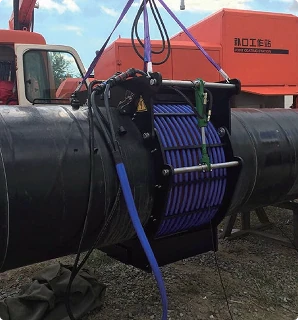
Coil Design Techniques for Tube and Pipe Heating
Tube and pipe heating is widely used in heat treatment, flaring, welding, and bending processes.
Design Objectives
- Achieve uniform circumferential heating
- Control the heated length
- Improve processing consistency
Design Priorities
(1)Ensure uniform circumferential temperature
Avoid:
- Overheating on one side
- Insufficient temperature on one side
(2)Control the axial heat-affected zone
Goals:
- Precisely control the heated length
- Reduce material waste
Coil Design Techniques for Gear Heat Treatment
Gears are complex workpieces that place high demands on coil design.
Design Objectives
- Ensure uniform hardening of the tooth surface
- Minimize distortion
- Improve wear resistance
Design Priorities
(1)Focus on the tooth surface area
Targeted heating of:
- Tooth tip
- Tooth flank
- Tooth root
(2)Avoid overheating
Prevent:
- Tooth surface burning
- Increased risk of cracking
Coil Design Techniques for Automated Production Lines
With the development of smart manufacturing, an increasing number of induction heating systems require integration with automated equipment.
Design Objectives
- Increase production efficiency
- Improve product consistency
- Reduce manual intervention
Design Priorities
(1)Improve repeatability
Ensure:
- Consistent heat input for every workpiece
- Minimized temperature fluctuation
(2)Adapt to continuous production
Key considerations:
- Long-term stable operation
- Rapid changeover capability
- Ease of maintenance
Comparison of Design Priorities Across Applications
| Application Scenario | Heating Rate Requirement | Temperature Uniformity Requirement | Localized Control Requirement | Continuous Operation Requirement |
| التقسية الحثية | Very High | High | Very High | High |
| اللحام الحثي بالنحاس | High | Very High | Very High | High |
| Forging Preheating | Very High | High | Lower | Very High |
| Metal Melting | Moderate | Very High | Low | Very High |
| Pipe Tube Heating | High | Very High | Moderate | High |
| Gear Heat Treatment | Very High | Very High | Very High | Moderate |
| Automated Production | High | Very High | High | Very High |
Application-Oriented Design Process
To achieve optimal heating results, the following design steps are recommended:
Step 1: Define Process Objectives
Determine:
- Heating temperature
- Heating depth
- Heating zone
Step 2: Analyze Workpiece Characteristics
Evaluate:
- Material type
- Workpiece dimensions
- Geometric shape
Step 3: Match Coil Configuration
Consider:
- Coil structure
- Diameter
- Number of turns
- Spacing
Step 4: Verify Heating Results
Focus on checking:
- Temperature uniformity
- Heating efficiency
- Product quality
Step 5: Continuous Optimization
Continuously optimize design parameters through testing and feedback to achieve optimal process performance.
Summary
The design of induction heating coils is not merely about optimizing a single parameter; rather, it requires a comprehensive balance of heating speed, temperature uniformity, energy efficiency, and production productivity based on specific application scenarios. Only by aligning coil design with actual process requirements can the advantages of induction heating technology be fully realized, ensuring a stable, efficient, and high-quality production process.